
Making in the Middle
Lighting Up History
Integrating Mathematics and Computational Thinking in the Science Classroom
Science Scope—May/June 2021 (Volume 44, Issue 5)
By Kristin Searle, Colby Tofel-Grehl, and Beth L. MacDonald
Computational thinking skills are central professional practices across science disciplines. Students need to engage in these skills during their K–12 education to be prepared for STEM careers. Weintrop and colleagues (2016) identified four major areas where mathematics and computational thinking connect to scientific practice: (1) working with data, (2) modeling and simulation practices, (3) using programming and computers to solve scientific problems, and (4) systems thinking practices. This article shares one project, a programmable paper circuit timeline that highlights the use of mathematics and computational thinking practices in the middle school science classroom while students learn science history. By programmable paper circuit, we refer to a circuit that is created using copper tape and light-emitting diode (LED) lights, but then is connected to a microcontroller so that it becomes programmable (see Figure 1). The copper tape is like a sticker, with adhesive on one side. However, the adhesive is not always conductive. This programmable paper circuit allows teachers to engage students in a learning activity that explores the concepts of energy conversion (from electric to light energy), energy storage, and polarity. Through the construction of this computational circuit, students learn about these concepts. In introducing the project, teachers are able to provide direct instruction around these concepts that is anchored in the phenomena students encounter with their circuits. Free detailed and standards-based lesson plans on the science content can be found at the Chaos Learning Lab (see Online Resources for link).
The Lighting Up History Project
Project overview
Middle school science teachers often seek to engage students in learning portions of the history of science and innovation as part of their work around the Next Generation Science Standards (NGSS) focused on Influence of Science, Engineering, and Technology on Society and the Natural World (NGSS Lead States 2013). To begin the activity, ask students what they want to know about a famous scientist or engineer or an invention. Sample questions might be: “Who wrote the first computer program?” or “Who is a famous epidemiologist?” Students can conduct research to answer their questions. The teacher may curate some readings from CommonLit (see Online Resources), a free resource for classroom readings for educators, and other sources. Lighting Up History is an excellent opportunity to engage students with scientists and engineers who look like them in terms of gender, race, ethnicity, and language. For the purposes of this article, we orient our project around Mae Jemison, the first Black female astronaut.
Based on their research, students plan, create, and program a paper circuit timeline of key events in the person’s life (see Figure 1). The lights are programmed to light up in sequential order of the events, beginning with the earliest life event. Working in small groups, students experiment with the programming of their timeline and troubleshoot the circuitry and their code. Through this process, students improve on their designs. If time allows, students can share their timelines for peer feedback. Completed timelines can be displayed. See safety note at the end of this article.
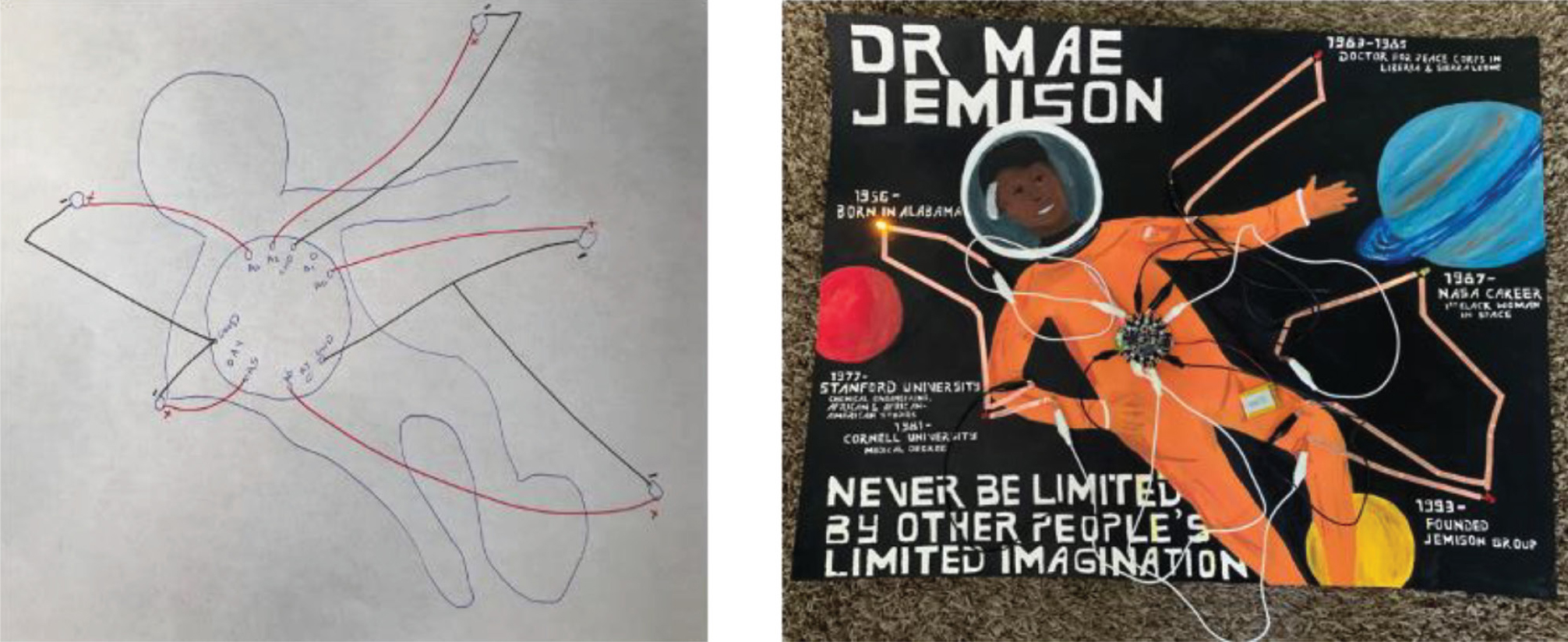
Left: circuitry diagram clearly distinguishing between positive and negatives lines. Right: completed Mae Jamison timeline with the LEDs programmed to light up in sequence.
Initial inquiry
This initial inquiry activity serves as both a circuitry refresher and an introduction to working with copper tape, LEDs, and batteries. After students watch a short video (“Getting Started With Copper Tape”; see Online Resources) on working with copper tape and their teacher reviews relevant safety precautions, students are given circuit templates to complete for simple, parallel, and series circuits (see Supplemental Materials). Students are asked to observe differences between the circuits, specifically how many batteries are required to illuminate the same number of LEDs in different kinds of circuits (simple and parallel circuit templates typically only require one coin cell battery, while a series circuit requires two). This allows for meaningful peer- and teacher-led discussions on energy transfer and the conversion of electric energy, stored in the battery, to be converted into light energy by channeling electrons through an LED bulb. Once students observe the difference between how many lights can be lit on a parallel and series circuit, the teacher can ask, “Why does the parallel circuit light up more bulbs?” We would expect students to reply with an explanation of how all the electrons in a series circuit that make it to the second bulb have gone through the first bulb. Further conversation should direct students to comparing and evaluating ideas around how the path and flow of electrons impacts resistance and other concepts.
The task
As described previously, students, working in collaborative groups of three to four, research any person of interest to them. Here, we use Mae C. Jemison as an example. After wondering about the first Black woman astronaut, students conduct research on Mae C. Jemison, who was the first Black woman to travel into space (see Mae Jamison: Astronaut Biography in Online Resources). Next, they are asked to select three to five key moments in Jemison’s life. With these key moments in mind, students work to create a light-up timeline of key events in Jemison’s life, such as her selection for NASA’s astronaut program in 1987. Each of the key points will be marked by an LED that will be programmed to light up in the sequence of events in Jemison’s life. To do so, students will have to figure out how long each LED should stay on and how much time should elapse before the next light turns on.
Timeline design
Students sketch both an artistic version of what they intend their timeline project to look like and a labeled circuit diagram illustrating how they will create functional circuits out of copper tape (see Figure 1). While there are limited options for creating a functional circuit, designing the circuit to work with the artistic design requires inquiry on the part of students. Teachers need to approve students’ circuit schematics before they move onto the next step to make sure the circuitry is connected correctly.
Circuit construction
After getting a design schematic drawn, students work on creating their timeline. While some artistic elements may need to be drawn before the timeline is laid out, we strongly suggest students work on the artistic elements after the circuit is complete. Following their circuit diagram, students first lay out their negative line, which runs underneath the negative lead (cathode) of each LED, and attach it to the microprocessor at a ground (GND) port. Second, they lay down each of their positive leads (anodes) and attach them to the microprocessor, using alligator clips between the tape and the microcontroller (better for reuse of the microprocessors later) or by connecting the tape directly to the microprocessors by either looping it through the hole on the microcontroller or folding the sticky side over on itself to create a sort of tail that can touch the microcontroller. Each positive line will attach to a separate port on the microcontroller. Third, with the positive and negative lines in place and attached to the microprocessor, students can add detailed elements to their drawing. The process of creating the circuit is similar to the creation of circuits in the initial inquiry activity. Students simply need to follow their labeled circuit diagram to make the appropriate connections. Now that the circuit is constructed, students must code their microprocessors to allow the light bulbs to turn on in the sequence they desire. Figure 2 shows one possible microcontroller that could be used for this project, the Circuit Playground Express by Adafruit, and how to attach lines of copper tape to the microcontroller using alligator clips.
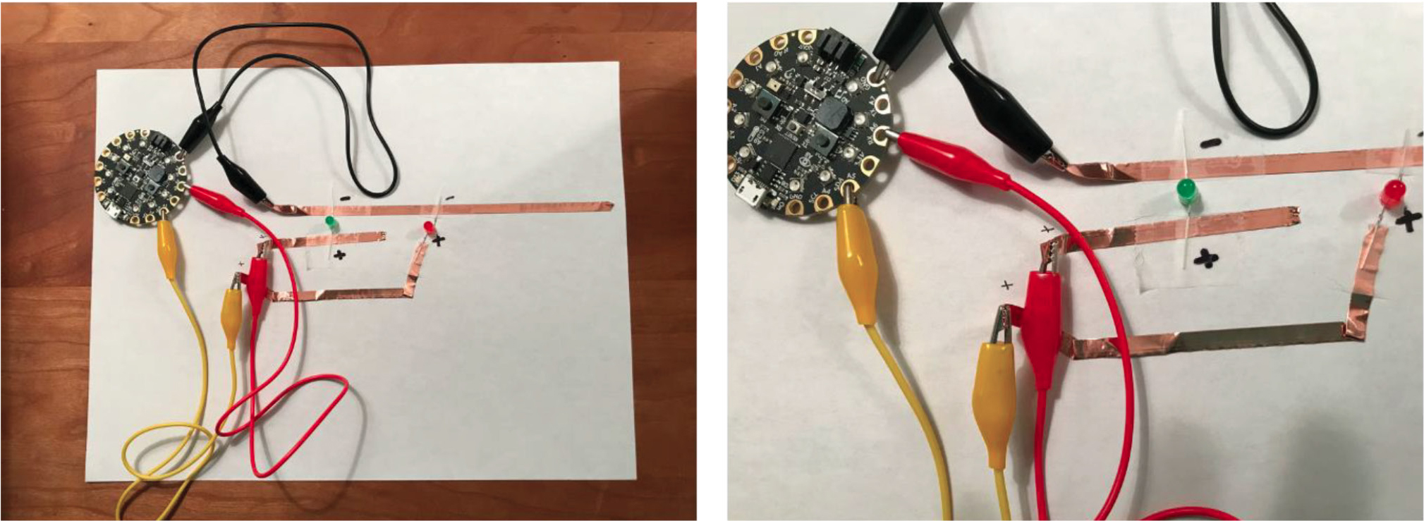
Left: one possible microcontroller that could be used for this project—the Circuit Playground Express by Adafruit. Right: lines of copper tape attached to the microcontroller using alligator clips.
Coding the microprocessor
The coding in this project should be easily completed by students with no programming experience, provided a microprocessor like the Circuit Playground Express that works with a blocks-based language is used. Text-based languages can be more challenging and are better suited to students with some programming experience. We suggest guiding students to (1) turn on all of their LEDs to confirm functional circuitry and (2) achieve a blink pattern for one of their LEDs. Figure 3 provides example code in the MakeCode environment, which works with the Circuit Playground Express microcontroller. Figure 3 shows code for (a) turning on all of the LEDs and (b) making one LED blink in MakeCode, which works with the Circuit Playground Express microcontroller. Different microprocessors work with different coding environments.
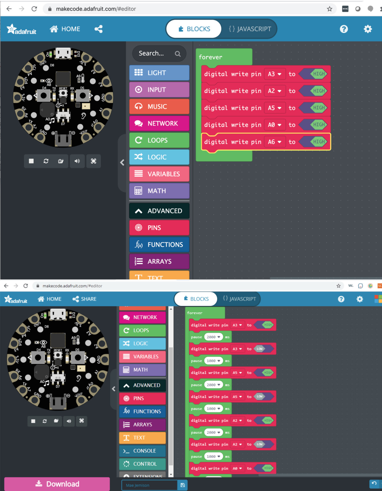
Sample code for (top) testing to make sure all the LEDs work and (bottom) programming the LEDs to blink. Because different projects will connect to different ports, the ports (e.g., A3, A5) will need to be adjusted accordingly.
The positive lead of each LED should be connected by an individual line of tape connected to an “A” port on microcontroller. The negative lead of the LED should be connected to the negative line of tape, which leads to a ground (GND) port on the microcontroller (see Figure 2). If a group’s LEDs do not all light up in Step 1, they will need to troubleshoot, looking for things like loose connections or flipped LEDs where the wrong lead is connected to the copper tape. Students can then work in their groups to figure out how to program their remaining LEDs, ideally by creating a set of step-by-step instructions (an algorithm) on paper and then translating these to the programming environment. Extended directions for the construction and programming of these circuits are available in Online Resources.
Differentiation
There are several opportunities for teachers to differentiate for students during this project. The easiest way to differentiate is by altering the number of LEDs that students need to use. Using fewer LEDs results in a less complex project, while using more LED’s makes the project more challenging. Another way teachers can differentiate this project is to create a template of a timeline circuit for students to use in their designs. Although this decreases the opportunities for students to be creative in their design, it also prevents some confusion. More advanced students can be challenged to do additional programming by adding sound to their timeline. Last, teachers can differentiate the readings provided to students in terms of both topics and ability level.
Integrating mathematics
When engaging students in this project, teachers can focus on proportional reasoning concepts, as outlined by the Common Core State Standards (CCSS-M; NGAC and CCSSO 2010; see also link in Online Resources). Proportional reasoning “is a way of reasoning about multiplicative situations” and is considered a “unifying theme in mathematics” (Van de Walle, Karp, and Bay-Williams 2019, p. 435). We focus on ratios as rates for this project. Ratios as rates involve relations between two different numbers, representing units such as time and length. When teachers engage students in the Lighting Up History Project, students use ratios to represent Jemison’s progress over time with a length model (time: length). Students can also represent ratios between milliseconds used in coding to determine when each LED lights up in sequence in relation to events in Jemison’s life in years (milliseconds: years) or the length between the LEDs (milliseconds: centimeters).
To bring forward ratio relationships in the science classroom, teachers can have students create tables where two varying units increase. For instance, if students are constructing ratio relations between milliseconds and centimeters, each column might represent changes between these units (milliseconds: centimeters) as they increase from 0:0 to 100:2 to 200:4 to 300:6 and so forth. In the science classroom, teachers can have students create a table like this before or after they make a paper circuit. The distance between the LEDs can be designed with a particular unit rate (e.g., 100:2, 50:1) in mind (see Figure 4). Supporting students during these activities might include asking questions such as, “How many milliseconds to you expect to have between LED lights at 55 years of age?” and “How does this show the relationship between years and milliseconds?” If they are struggling, teachers should focus on changes between rates that can be drawn in a tape diagram where one line represents a quantity (e.g., one foot-length line represents 55 years) and an identical line below represents a different quantity (e.g., one foot-length line represents 2,000 milliseconds). Through activities like these, students develop composed units where the ratio (e.g., years:milliseconds) is thought of as one unit, allowing students to understand ratio relationships without tape diagrams or other materials.
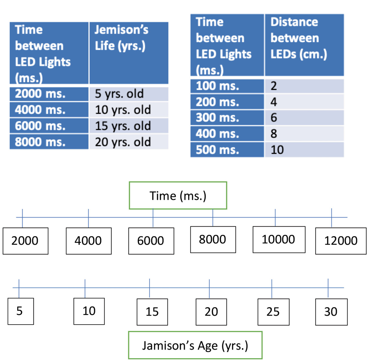
Demonstration of how ratios might be used in this project.
Integrating computational thinking
Students will have to evaluate multiple possible circuit designs when creating their timeline project, which connects to computational thinking and problem- solving practices. This project also asks students to engage with writing algorithms (the code to turn on their lights) and troubleshooting and debugging both their circuits and their code.
Assessment
Table 1 provides one possible rubric for summative assessment on the various components of the project. Each component of the rubric leading up to the overall design provides suggestions for formative assessment of the different project phases.
Supply list and cost
Materials for the Lighting Up History Project vary considerably in cost (see Table 2). We encourage teachers to comparison shop for the best prices. Almost any programmable, sewable microcontroller will be functional. We have tested this project in classrooms with both the LilyPad Arduino microcontroller and the Adafruit Circuit Playground Express. The microprocessors and accessories (USB cords and batteries) are the most expensive component of the project, but they can be retained by the teacher for reuse. While prices listed in Table 2 do not reflect educator discounts, most vendors offer an educator discount as well as volume pricing.
Modifying for online or hybrid learning
Because this project is supported with many video resources, it is easily adaptable to hybrid and online learning environments. Students could brainstorm at home and conduct research about their chosen scientist. Then ideally, students could complete the circuit templates in the classroom or in a synchronous online session. Another option is to have students submit an online assignment for each completed circuit template so the teacher can provide feedback. Groups could collaborate on answering the following two questions based on Mae Jemison’s life:
1. Describe the events from Mae’s story that you are going to make your timeline about.
2. List out three to four moments/events from Mae’s story that you are going to put on your timeline.
Then students could create their timeline together in the classroom. Alternatively, students could complete individual timelines at home, but this significantly increases the material costs. Programming can happen anywhere with an internet connection, though it does eventually need to be downloaded onto the microcontroller for the timeline to light up.
Conclusion
The Lighting Up History Project provides an opportunity for project-based science in the middle school classroom, with a particular focus on the integration of mathematics and computational thinking. While computational thinking has been defined in many ways, we emphasize some of the aspects teachers can focus on, such as breaking a problem down into multiple steps, troubleshooting and debugging, and writing simple algorithms (step-by-step instructions) to turn on the timeline’s LEDs. The project also allows students to learn about energy conversion (from electric to light energy), energy storage, and polarity, as well as science history.
Important safety note: The Lighting up History Project is a relatively low-risk project, but school and district safety guidelines should be followed. One concern is that the edges of the copper tape can be sharp and potentially cause a paper cut. Students should be cautioned about this possibility and work accordingly. Students will also be using scissors to cut the copper tape. Standard scissor safety precautions should be followed. •
Acknowledgments
This material is based upon work supported by the National Science Foundation under Grant No. (1758823). Any opinions, findings, and conclusions or recommendations expressed in this material are those of the author(s) and do not necessarily reflect the views of the National Science Foundation.Online Resources
Chaos Learning Lab—https://chaoslearninglab.weebly.com/project-e-stitch.html
Common Core State Standards for Math—http://www.corestandards.org/Math/
CommonLit—commonlit.org
Getting Started With Copper Tape—https://chibitronics.com/copper-tape-tutorial/
Extended directions for construction and programming of circuits—https://chaoslearninglab.weebly.com/resources.html#Video
Mae Jemison: Astronaut Biography—https://www.space.com/17169-mae-jemison-biography.html
Supplemental Materials
Kristin Searle (kristin.searle@Usu.edu) is an assistant professor in the Department of Instructional Technology & Learning Sciences, Colby Tofel-Grehl is an associate professor in the School of Teacher Education & Leadership, and Beth L. MacDonald is an associate professor in the School of Teacher Education & Leadership, all at Utah State University in Logan.
Instructional Materials Maker Spaces Makerspace Technology