
feature
Chemical Cargo Carrier
An engineering design challenge using Newton’s laws
The Science Teacher—March/April 2023 (Volume 90, Issue 4)
By Marta Stoeckel, Angela Peterson, Lisa Ortmann, and Gillian Roehrig
In the Next Generation Science Standards (NGSS Lead States 2013), science teachers are challenged to make meaningful links between science and engineering. Engineering design not only provides opportunities to integrate engineering and science but also makes learning more authentic and relevant by grounding the learning in a meaningful context (Kelley and Knowles 2016). This article describes a unit developed for our ninth-grade physical science classes centered on an engineering design challenge in which students learn about forces to develop a scale model of a cargo carrier to protect an egg in a crash.
STEM integration model
We wanted to integrate engineering to promote deeper learning and to engage students who had not previously been successful, so we designed this unit using a STEM integration framework (Moore et al. 2014a) that promotes meaningful integration of the science and engineering practices (NGSS Lead States 2013). This framework has six tenets for quality STEM curriculum that guided our planning throughout the unit (Moore et al. 2014b). Given that many familiar experiences can be described using Newton’s laws, we used this framework to redesign our force and motion unit. We focused on HS-PS2-3, which calls for students to design a device to minimize forces on an object during a collision (NGSS Lead States 2013). Our nine-day unit addressed Newton’s laws through a design challenge in which students developed a cargo carrier model that protects an egg during a crash. See Figure 1 for an overview.
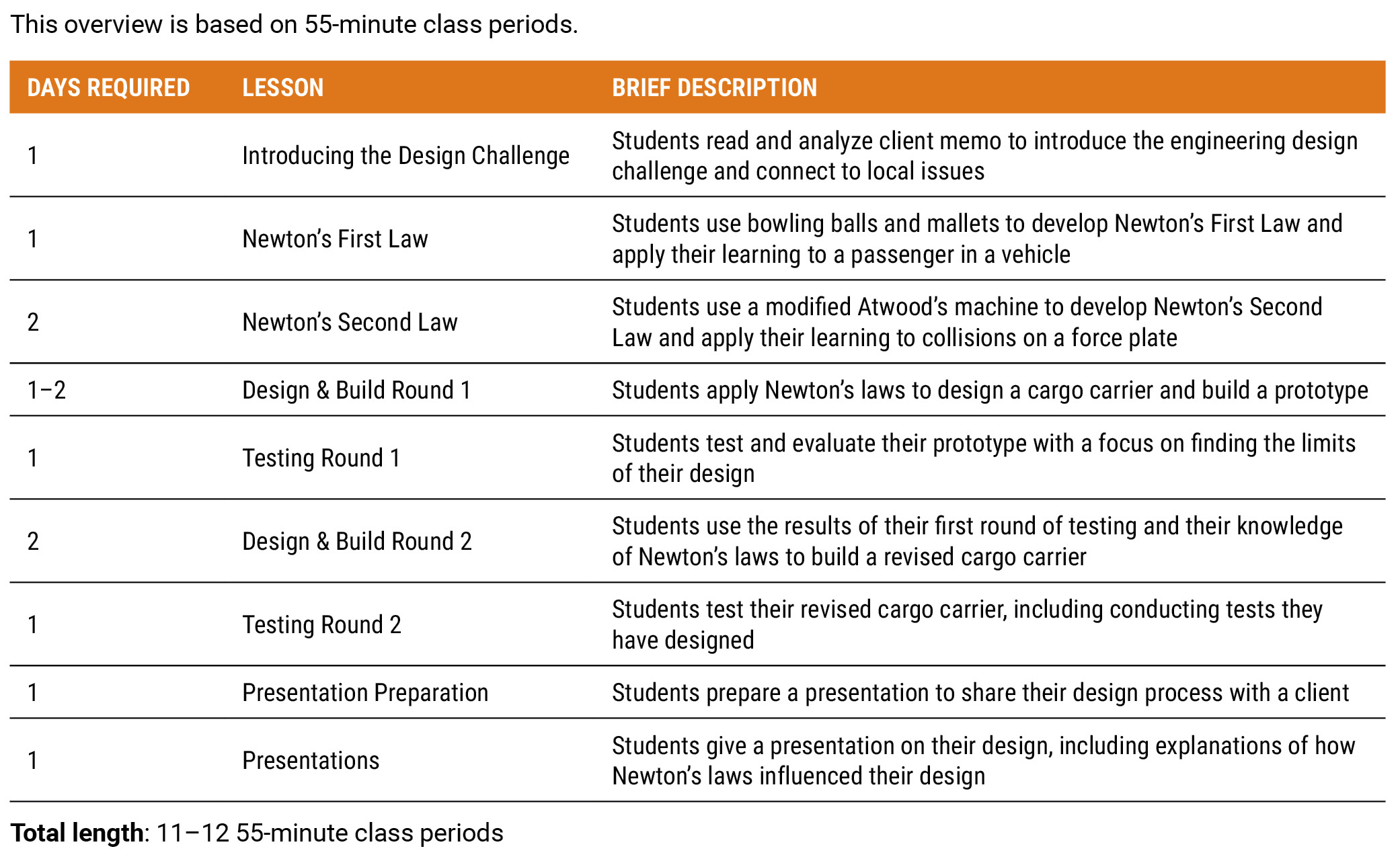
Unit Overview.
The first lesson introduced an engaging context (first tenet of the framework) (Moore et al. 2014b) and a compelling design task (second tenet of the framework). We showed students maps of contaminated sites—identified by the Environmental Protection Agency (EPA)—located in our schools’ attendance areas. This connected the design challenge to local environmental issues and prompted a discussion of the need to safely transport waste to sites where the waste can be safely processed and disposed of.
Students then analyzed a memo (Figure 2) from a fictitious chemical transport company that served as the client. The client asked students to design a scale model of a chemical cargo carrier that can be attached to existing vehicles. This narrowed students’ focus to how the barrel of hazardous chemicals (egg) will be loaded and transported rather than focusing on issues that have limited connections to the target content (e.g., how to ensure the vehicle travels in a straight line). The challenge emulates the way professional engineers often integrate their designs with existing technologies. The memo also provided a budget and specified that the design would be tested only in a front-end collision.
Client letter.
Twin Cities Chemical Transport Co.
100 Main Street
St. Paul, MN 55110
Titan Engineering Associates,
As part of efforts to clean up Superfund sites near Oakdale, several area chemical companies have found new locations to process and dispose of hazardous waste. We recently received the contract to transport the chemical waste to these new sites.
We would like your help developing a cargo carrier to safely transport chemical waste. You will design a scale model of a cargo carrier, and we will select designs to develop into a full-size cargo carrier. The cargo carrier will need to fit one standard barrel of waste and must be able to attach to our existing trucks. The cargo carriers also need to be cost-effective, so you will have a budget. We are especially concerned about crashes, so your tests should focus on how well your design protects the barrel in a collision.
Your help will make it possible for us to safely transport hazardous waste and for area companies to responsibly deal with excess chemicals. We truly appreciate all of your hard work designing a new cargo carrier.
Sincerely,
Twin Cities Chemical Transport Co.
We wrote the memo to call for a specific level of performance, rather than challenging students to optimize their design. The goal of the project was to provide our client with a range of viable options, which promoted a collaborative rather than competitive environment. This also encouraged students to take risks with their designs since they were not concerned with how their design would compare with their peers’ designs.
To connect science content to the design task, students brainstormed concepts they would need to learn. Students easily recognized that they needed to learn about forces during collisions, allowing us to introduce Newton’s laws as a lens to analyze collisions.
For these lessons, we used standard activities to introduce Newton’s first and second laws but provided opportunities for students to connect their learning to the design challenge. Students began working in groups of three (created with a random number generator) that they remained with through lesson 5. One goal of these lessons was to ensure students saw Newton’s laws as intertwined in the design challenge to meet the third tenet of the framework, which calls for activities that deepen students’ science learning (Moore et al. 2014b).
For Newton’s first law, students determined how to change the motion of bowling balls by tapping them with rubber mallets to conclude the bowling ball only accelerates when there is an unbalanced force, an activity from the Modeling Instruction materials (Jackson et al. 2008). To connect this to the design challenge, we had students use a 100 g mass to represent a passenger in a dynamics cart, then observe and explain the motion of the passenger in several scenarios (Figures 3 and 4).
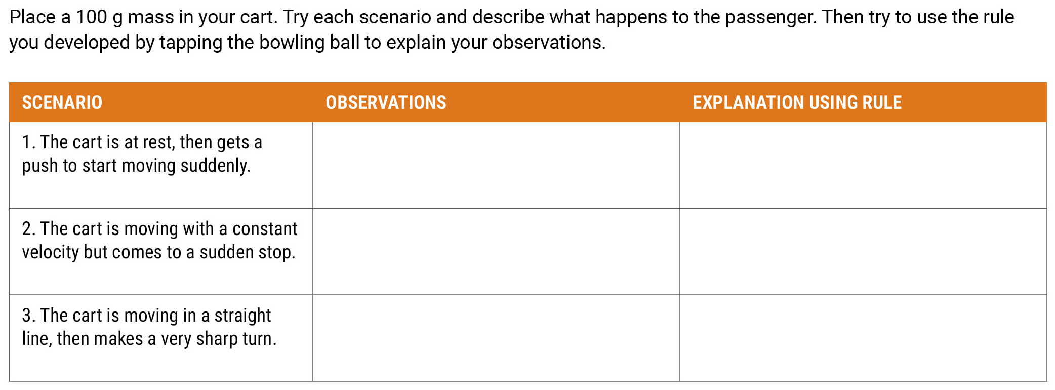
Lesson 2 handout.
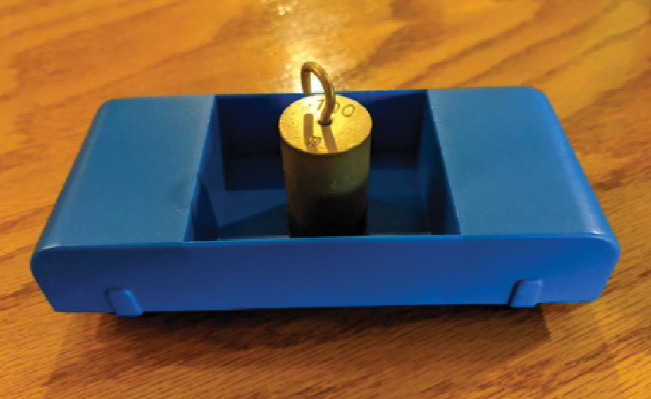
Equipment for passenger in cart activity.
For Newton’s second law, students collected data with a modified Atwood machine to find a relationship between net force and acceleration. Students tied a string to a cart on a track, then draped the string over a pulley and attached a mass hanger to the end of the track. Students added masses to the hanger, then calculated the force of gravity on the hanger to determine the net force on the cart-hanger system. Students then released the hanger and recorded how long it took the cart to travel a set distance to calculate the acceleration of the system. Students then transferred some mass from the hanger to the cart and repeated this experiment to make a graph of acceleration vs. force and determine that the slope of their graph is the inverse of the total mass of the system.
To learn about collisions, students dropped a basketball first on a bare force plate, then on a force plate topped with a pillow. The force plate recorded a force vs. time graph, showing the force was larger for the bare plate but spread over a larger time with the pillow, as shown in Figure 5. Students recognized that the basketball had the same change in velocity in both cases, but the longer time with the pillow resulted in a smaller acceleration and a smaller force. Next, students brainstormed existing technologies, such as air bags and crumple zones, that rely on this principle.
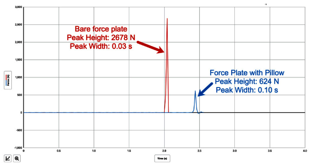
Force vs. time graph for basketball on force plate.
Students next applied their knowledge to design and build their first iteration of a cargo carrier model. Since communication and teamwork are tenets of the framework (Moore et al. 2014b), we had two major goals. First, we wanted to ensure that every student had opportunities to contribute to the group. Second, we wanted students to articulate connections between their science learning and design.
First, students worked individually to come up with ideas for the cargo carrier, which supported differentiation by ensuring that students with longer processing times had time to brainstorm ideas. Students recorded their ideas in an evidence-based reasoning organizer (see Figure 6) based on the claim-evidence-reasoning framework (Moore and Douglas 2014). Instead of a claim, students recorded their idea, using sketches, written descriptions, or a combination based on the modality they were most comfortable with. The evidence was science principles, such as Newton’s laws, and the reasoning was replaced with a justification for how the evidence supported the idea and required students to articulate how their science learning supported their ideas. Figure 7 is an example of student work using this organizer.
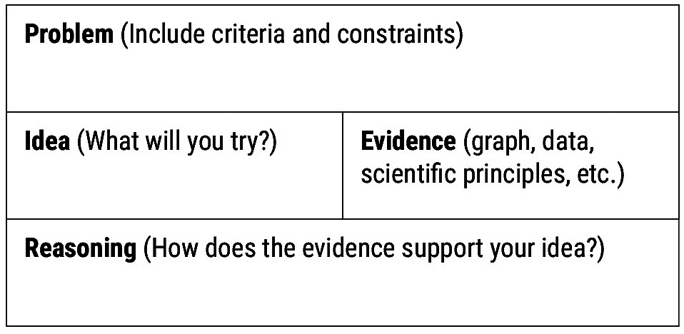
Evidence-based reasoning organizer.
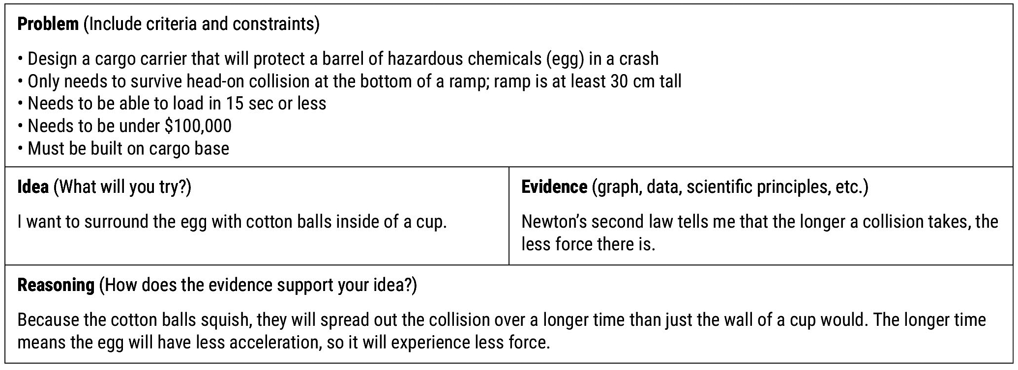
Student sample of evidence-based reasoning organizer.
Students next moved into their groups to come to a consensus on a design. Each group worked on a large whiteboard, giving them a space that was accessible to all group members to encourage collaboration. The whiteboards also supported differentiation by having students share their idea through sketches, written descriptions, verbal descriptions, or a combination. Once groups were satisfied with their design, we required students to verbally explain their design decisions to the teacher using Newton’s laws.
Once a group was ready to build, we provided a base made from a 6-inch board (Figure 8). The bases were covered with a layer of duct tape for easy reuse. The bases had heavy-duty hook-and-loop fasteners (Figure 9) that attached to the preassembled trucks (Figures 10, 11, and 12). Since it was quick to swap the base, we only needed a few trucks. Groups also tracked their expenses using a price list to stay below the budget established in the memo (Figure 13).
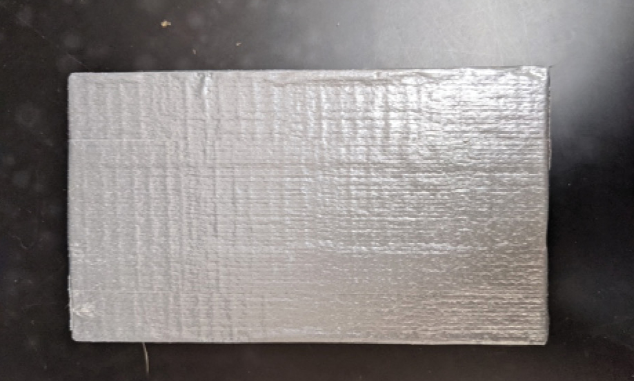
A taped cargo base ready for students to build on.
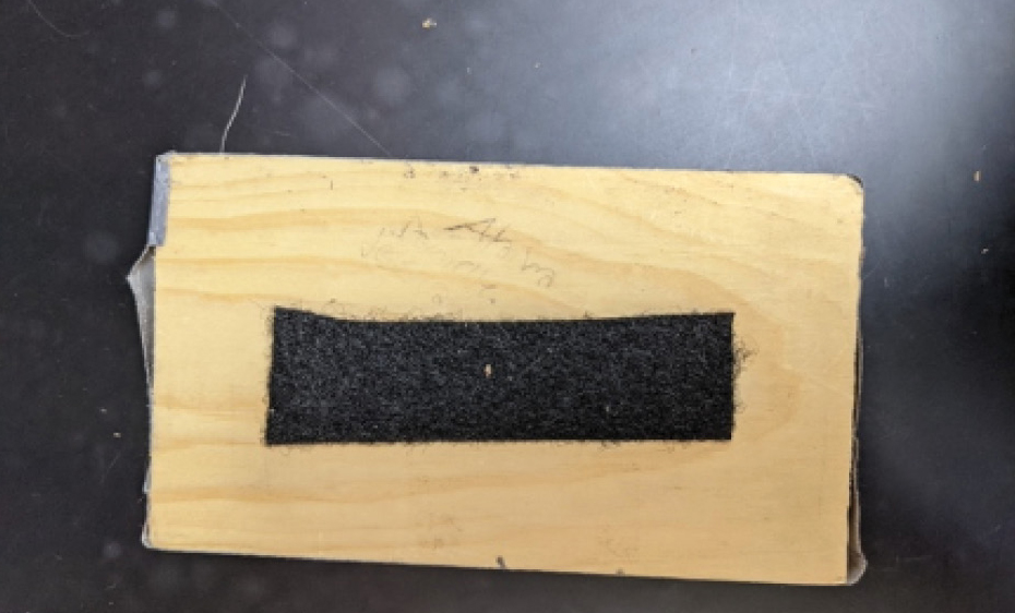
Hook-and-loop fastener on the bottom of a base.
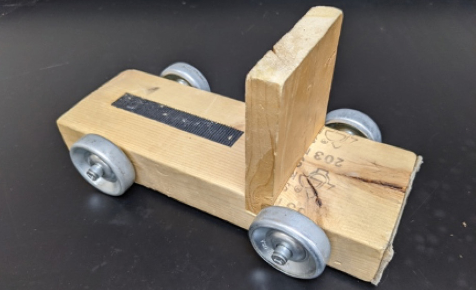
Truck without a cargo base.
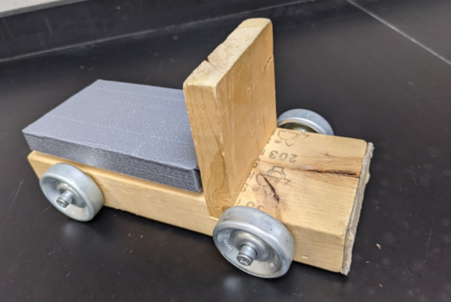
Truck with cargo base attached.
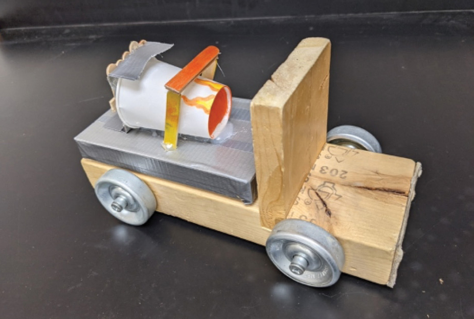
Example student cargo carrier.
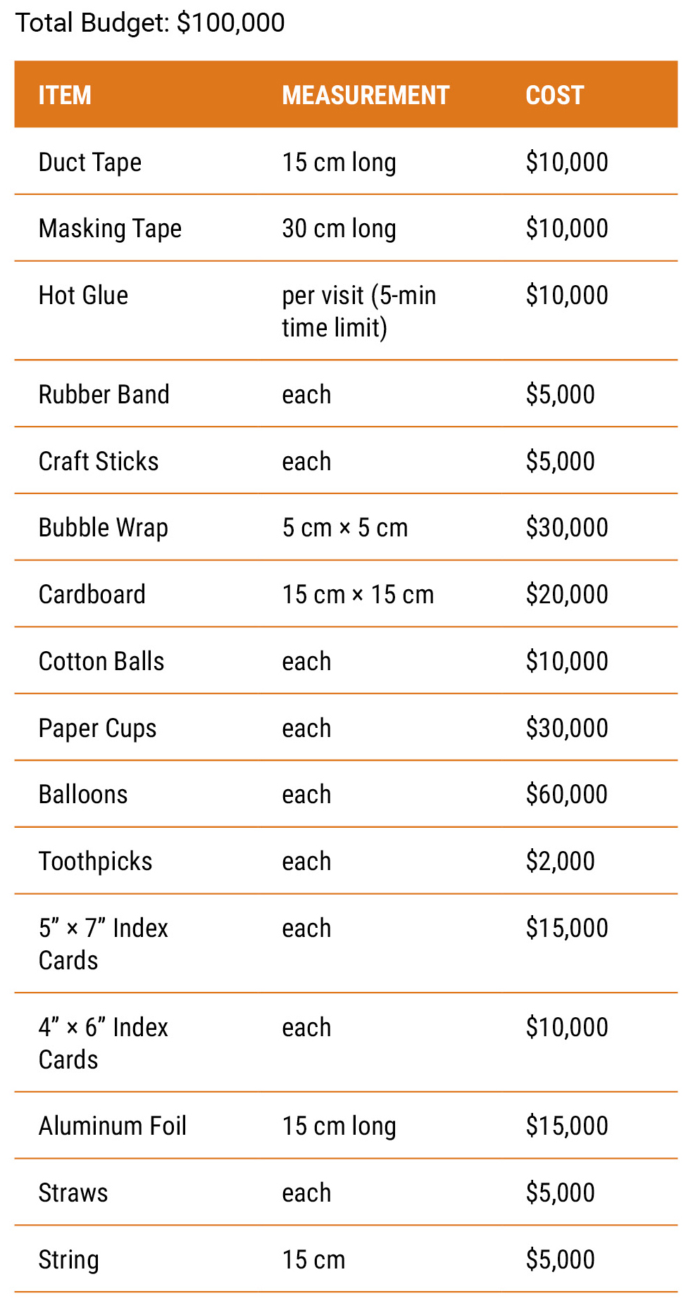
Materials price list.
Lesson 5: Testing round 1 (one class period)
For this lesson students knew they could refine their designs in line with the frameworks tenet for students to learn from failure (Moore et al. 2014b), so we made explicit that the goal of the tests was to find flaws of each design so it could be improved. This framing ensured that every group would have a successful test and encouraged an atmosphere where groups exchanged ideas.
Since an actual cargo carrier would need to be loaded efficiently, groups timed how long they needed to get the egg into the carrier as part of the test. Students then determined the mass of the truck with an egg loaded into their carrier. For the main test, we set up ramps supported by books so we could adjust the height. We spread out plastic sheeting under the ramps for cleanup. Groups took turns attaching their carrier to a truck and rolling it down the ramp while a student held a Vernier force plate vertically at the bottom of the ramp for a collision. After each trip down the ramp, groups recorded the state of their egg based on three degrees of success: fully intact, membrane intact, and broken but contained. Students also recorded the time it took the truck to reach the bottom of the ramp and the maximum force recorded by the force plate. Since the goal was to find the failure point of the design, groups raised the height of their ramp and repeated the test until their egg broke. For the ramp height where the egg broke, students used the length of the ramp and the time for the truck to reach the bottom to calculate the velocity of the truck just before the collision. Students then used the mass of the loaded truck and the maximum force during the collision to find the maximum acceleration of the truck during the collision.
Lesson 6: Design and build round 2 (one to two class periods)
Students next designed and built a second iteration of their cargo carrier so they could apply what they learned from their first design’s failures. This lesson was similar to lesson 4 with students brainstorming individually and then as a group before building, with students again communicating in multiple modalities. We took two steps to encourage groups to revise their designs. First, we created new random groups of three. We explained that our goal was to generate as many effective designs as possible for our client and changing groups meant that they would be able to combine ideas in new ways.
Second, we asked students to design at least two new tests in addition to the original ramp test. Students recognized that testing only a front-end collision is limited, especially if there were mishaps during the initial tests, such as trucks rolling off the side of the ramp. Each group submitted materials and a procedure for each new test to ensure their proposal was safe and the materials were available. Students invented a variety of tests, such as placing their cargo carrier at the bottom of the ramp and rolling another truck down to simulate a rear-end collision or causing a rollover by placing a narrow wedge on the ramp to force one side of the truck upward. This gave students ownership over the tests and motivated changes to the initial design since they needed to protect the cargo under more conditions.
Lesson 7: Testing round 2 (one class period)
Students completed their second round of testing during lesson 7. We tasked students with collecting the data needed to clearly communicate the strengths and limitations of their design to our client. Since this lesson included tests students had designed, groups needed to figure out the types of information to record. We asked students to brainstorm data, observations, and records they could collect to help our client understand the results of their tests. In addition to the state of their egg and other observations from their tests, students suggested data such as photos of their design and videos of their tests. Students began by conducting the tests they designed. Once those were completed, students repeated the ramp test from lesson 5 until their egg broke.
Lesson 8: Assessment (two class periods)
As an assessment, we asked each group to prepare a presentation describing and evaluating their final design, addressing the framework’s tenet of emphasizing communication and teamwork (Moore et al. 2014b). Because students changed groups, we only required them to discuss their final design, though we did encourage groups to discuss what they learned in the first iteration. The most important part of the presentation was connecting Newton’s laws to both their design decisions and their observations from the tests. In this lesson students used one class period to prepare the presentation and one class to present. We evaluated these presentations using the rubric in Figure 14 (see Online Connections). We intentionally did not score students on how well their design performed, only on how clearly students communicated their decisions and analysis to ensure every group could be successful, even if their design was ineffective.
Conclusion
Grounding our unit on forces in an engineering design challenge not only allowed us to bring engineering practices into our classrooms but also proved engaging for students. The real-world context of the unit motivated previously disengaged students. Framing the design challenge around clear communication, rather than a competition, fostered a collaborative classroom environment and encouraged students to take risks and learn from failures. In addition, continuously asking students to explain their thinking helped draw meaningful connections between the science content and the design challenge, as well as deepen students’ understanding of Newton’s laws. As one student explained “You can actually understand because you need to know in order to do stuff and be successful with it.”
Acknowledgments
This material is based on work supported by the National Science Foundation under grant number NSF DUE-1238140. Any opinions, findings, and conclusions or recommendations are those of the authors and do not necessarily reflect the views of the National Science Foundation.
Thank you to Scott Sturm, Erik Tvedten, Kent Gordon, and Scott Lotze of North St. Paul-Maplewood-Oakdale Public Schools for sharing their modifications.
Online connections
Figure 14. Final presentation rubric: https://bit.ly/3ZaFyhS
Marta Stoeckel (mrstoeckel@gmail.com) is a science content specialist at North St. Paul – Maplewood – Oakdale Schools, North St. Paul, MN. Angela Peterson (angela.peterson@spps.org) is a physics teacher at Washington Technology Magnet School in St. Paul, MN, Lisa Ortmann (lisaortmann@gustavus.edu) is an assistant professor of education at Gustavus Adolphus College in St. Peter, MN, and Gillian Roehrig (roehr013@umn.edu) is a professor of STEM education at the University of Minnesota in St. Paul, MN.
Curriculum Engineering Instructional Materials NGSS Physical Science Physics Science and Engineering Practices STEM High School